Robotic Arm Electrical Interface
1 Base electrical interface
1.1 Introduction to the base
A,Figure 1-1 shows the front ports and buttons on the base:
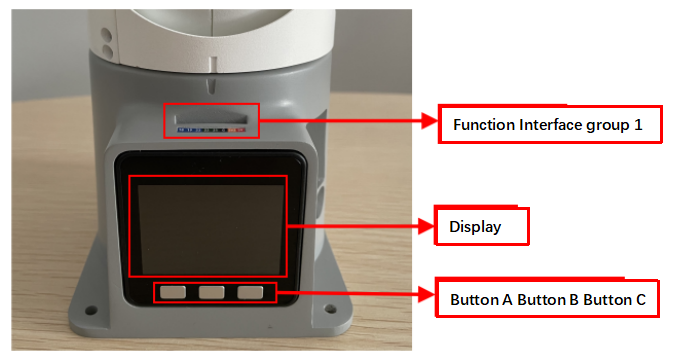
Figure 1-1 Front view of the base
B, Figure 1-2 shows the ports on the left of the base:
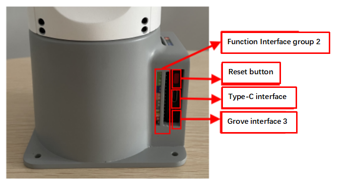
Figure 1-2 Left view of the base
C, Figure 1-3 shows ports on the right of the base:
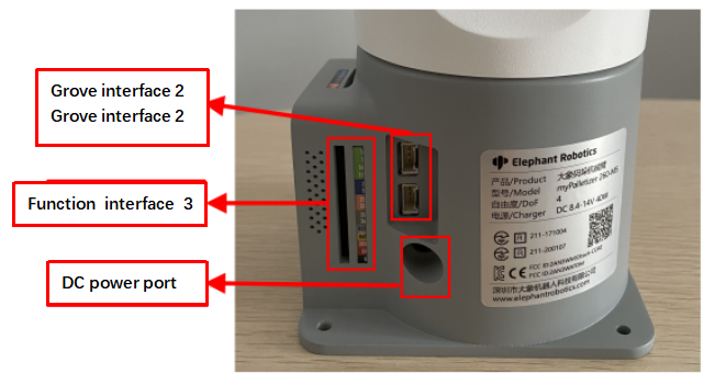
Figure 1-3 Right view of the base
1.2 Description of the bottom electrical interface
Note: Function interface group is 2.54mm Dupont interface, external can use 2.54mm Dupont wire.
A. Table 1-1shows the definition of each interface in a functional interface group 1.
| Tag | Signal | Function | Note |
|---|---|---|---|
| 18 | G18 | - | Temporarily not open |
| 19 | G19 | 3.3 V-out-PNP output /3.3 V-int input | |
| 23 | G23 | - | Temporarily not open |
| 22 | G22 | 3.3 V-out-PNP output /3.3 V-int input | |
| 21 | G21 | 3.3 V-out-PNP output /3.3 V-int input | |
| G | GND | Motherboard power signal ground | |
| 3V3 | 3V3 | DC3.3 V power supply | |
| 5V | 5V | Power supply, DC5V |
Table 1-1 Functional interface group 1
B. The definitions of interfaces in functional interface group 2 are the same as those in functional interface group 3, as shown in Table 1-2.
| Tag | Signal | Function | Note |
|---|---|---|---|
| 3 | G3 | 3.3 V-out-PNP output /3.3 V-int input | This parameter is unavailable when usB-Type-c is used |
| 1 | G1 | 3.3 V-out-PNP output /3.3 V-int input | This parameter is unavailable when usB-Type-c is used |
| 16 | G16 | - | Temporarily not open |
| 17 | G17 | - | Temporarily not open |
| 2 | G2 | 3.3 V-out-PNP output /3.3 V-int input | |
| 5 | G5 | 3.3 V-out-PNP output /3.3 V-int input | |
| 25 | G25 | 3.3 V-out-PNP output /3.3 V-int input | |
| 26 | G26 | 3.3 V-out-PNP output /3.3 V-int input | |
| 35 | G35 | 3.3 V-int input | |
| 34 | G34 | 3.3 V-int input | |
| RST | RST | Master reset | |
| BAT | BAT | - | Temporarily not open |
| 3V3 | 3V3 | DC3.3 V power supply | |
| 5V | 5V | Power supply, DC5V | |
| G | GND | Motherboard power signal ground |
Table 1-2 Functional interface groups 2 and 3
Description: Figure 1-5 shows other functions of the interface. If other functions are used, the I/O function is unavailable.
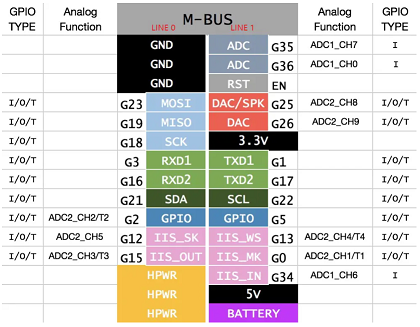
Figure 1-4
C. Power DC interface: The myPalletizer is powered by a 6.5mm od, 2.0mm OD, and a manufacturer's 8.4V 5A DC power adapter
D. Grove interface: Figure 1-5, Figure 1-6, and Figure 1-7 show the Grove interface definitions
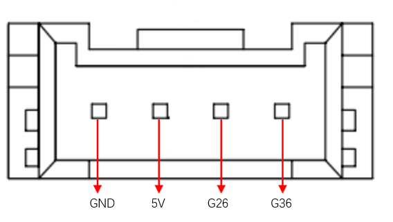
图1-5 Grove port 1
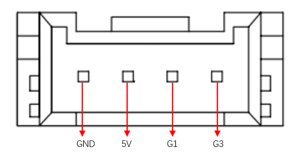
图1-6 Grove pin port 2
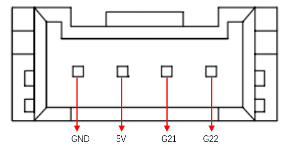
图1-7 Grove port 3
E. type C interface: used to communicate with the PC. G1 and G3 ports are occupied when this interface is used.
F. Reset button: used when the main control system is reset
G. Buttons A, B, and C: Cooperate with the display
H. Display: The 2-inch IPS screen can be used to display mycobot communication status and adjust robot origin with buttons.
2 Mechanical arm end electrical interface
2.1 The end of the manipulator is introduced
A. Figure 2-1 show the side interfaces at the end of the manipulator.
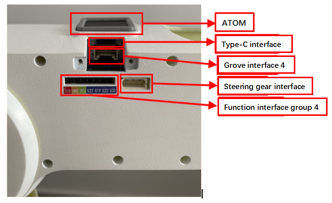
Figure 2-1 End of the manipulator
2.2 Description of terminal electrical ports
A. Table 2-1 shows the definition of each interface in a function interface group 4.
| Tag name | Signal name | Function | Note |
|---|---|---|---|
| 5V0 | 5V | Power supply, DC5V | |
| GND | GND | Motherboard power signal ground | |
| 3V3 | 3V3 | DC3.3 V power supply | |
| G22 | G22 | 3.3 V-out-PNP output /3.3 V-int input | |
| G19 | G19 | 3.3 V-out-PNP output /3.3 V-int input | |
| G23 | G23 | 3.3 V-out-PNP output /3.3 V-int input | |
| G33 | G33 | 3.3 V-out-PNP output /3.3 V-int input |
Table 2-1 Functional port group 4
B. Type C interface: used to communicate with PC and update firmware.
C. Grove interface 4: Figure 2-2 shows the definition of Grove interface 4
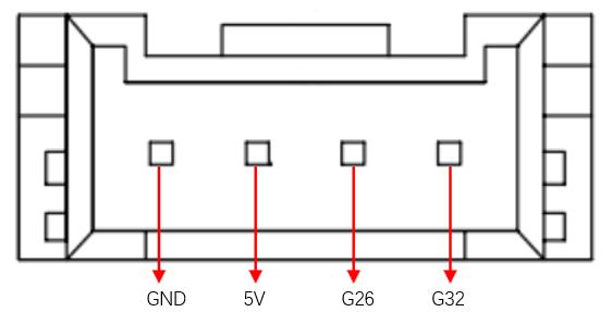
Figure 2-2 Grove port 4
D. Steering gear interface: used for expanding the end of the gripper, currently supporting the use of adaptive gripper.
E. Atom: For 5X5 RGB LED (G27) display and button function (G39)